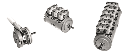
A Low Torque, Precision Component with Adjustable Snap-Action Switching

- Adjusts to any desired dwell angle from 3° to 357 ° of shaft rotation
- Switch settings infinitely adjustable with respect to shaft
- Switch setting independent of other switches in stack
- Switching angles cane be set and locked in seconds
- Adjustments can be made while shaft is stationary or rotating
- Only 1-1/16″ diameter; equivalent of BuOrd Size 11
The PMC Model CS 402 Cam Switch combines in a compact 1-1/16″ diameter unit all the functions of a conventional plate cam, cam follower and snap-action switch. External screwdriver adjustments permit rapid setting of any desired switch make angle. Designed for timing, indication, control, computation and other applications where snap action switching is required, it permits the instrument and servo designer to meet specific application requirements through use of a single component that can be mounted in a gear assembly in a manner similar to synchros, potentiometers and other rotating shaft components. Because the CS 402 Cam Switch replaces conventional cam mechanisms, independently mounted switches and their associated hardware, it provides significant savings in design, fabrication and assembly time. Its small size permits significant improvements in miniaturization of the end product.
Adjustment of the CS 402 Cam Switch can be accomplished rapidly and precisely while the shaft is either stationary or rotating, by means of two external adjusting screws, and can be completed within seconds. As a result, it provides a unique means for ‘trimming-in’ required performance in production or during equipment maintenance. Conveniently located locking screws maintain switch settings under all conditions of shock and vibration encountered by military equipment. Model CS 402 Cam Switches incorporate standard type SPDT, sub miniature, snap switches and are available as single-switch units, or as multi-ganged types with as many as 10 switches. Both single and multi-stack types can be supplied with double-ended shaft for mounting dial or indicator. All types meet applicable requirements of MIL-E-5400. Complete mechanical and electrical specifications are given below.

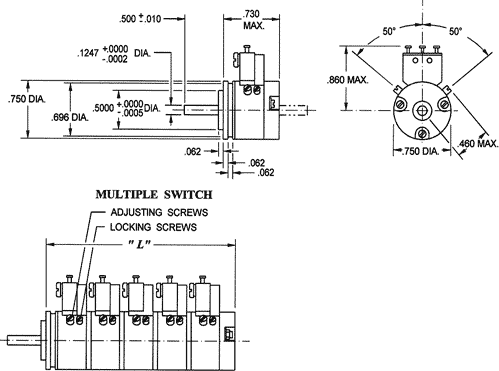
| Part No. | No. Of Switches | Dim. “L” (In. Max.) | Inertia (OZ. IN. Sec. ²) | WT. (OZ.) |
| CS402-1 | 1 | .800 | 0.6×10⁻⁵ | 1.4 |
| CS402-2 | 2 | 1.300 | 1.2×10⁻⁵ | 2.1 |
| CS402-3 | 3 | 1.800 | 1.8×10⁻⁵ | 2.8 |
| CS402-4 | 4 | 2.300 | 2.5×10⁻⁵ | 3.5 |
| CS402-5 | 5 | 2.800 | 3.1×10⁻⁵ | 4.3 |
| CS402-6 | 6 | 3.300 | 3.7×10⁻⁵ | 5.0 |
| CS402-7 | 7 | 3.800 | 4.3×10⁻⁵ | 5.7 |
| CS402-8 | 8 | 4.300 | 4.9×10⁻⁵ | 6.5 |
| CS402-9 | 9 | 4.800 | 5.5 x10⁻⁵ | 7.2 |
| CS402-10 | 10 | 5.300 | 6.1×10⁻⁵ | 8.0 |
SPECIFICATIONS:
Electrical Ratings:
115/230 vac 5 amp, inductive and resistive
30 vdc resistive, sea level 5.0 amp
resistive, 50,000 ft 5.0 amp
inductive, sea level 3.0 amp
inductive, 50,000 ft 2.5 amp
Max. Inrush 24 amp
Mechanical Data:
Shaft rotates on precision ball bearings
Shaft End Play 003 in., max.
Shaft Pilot Run out 001 in., max., T.I.R.
Temperature Range -65ºF to +250ºF
Make-Break Differential 1.5º max.
Operating Torque 1.5 oz.-in., max., per switch (see note)
NOTE: peak torque occurs at switch actuation. With all switches in a multi-switch unit set to identical on-off positions, the total maximum torque will not exceed n x 1.5 oz-in., (where n is the number of switches in the stack). With different switch settings the total maximum torque may be as low as 0.5 x n x 1.5 oz-in., depending upon the specific on-off settings.
VARIATIONS FOR PARTICULAR REQUIREMENTS
Precision Mechanisms Corporations will be pleased to quote on variations for the CS 402 Cam Switch for special requirements. Readily available variations include:
- non-standard shaft extension
- double-ended shaft extension
- ultra low differential switches
- multi-switch units mounted in gear train mechanisms for specific switching functions, with or without motor drive